没有丢点情况的凹版印刷
静电辅助印刷系统(ESA)通常用于提高印刷质量,因为它有助于消除丢点情况的发生。但是,如果印刷人员选择了错误的ESA系统或使用不当,它本身反而会引起凹版印刷机的问题。
此文摘由 ANSGAR WESSENDORF撰写
您可以在Flexo Gravure Global Site网站上找到原始文档
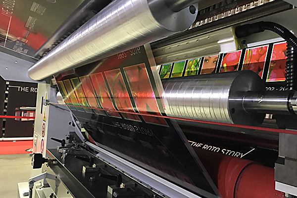
The ESA principle with respect to gravure printing presses for decor and flexible packaging On modern gravure printing presses for decor and flexible packaging, electrostatic printing assist is standard equipment. ESA is decisive in ensuring that the ink is transferred from the cells of the gravure cylinder to the substrate, thus improving the quality of the print itself. However, setting and operating the electrostatic printing assist improperly can lead to problems in the print run. Selecting the right system and observing a few basic rules can prevent such problems arising with respect to gravure printing presses. Charging the impression roller with an electrostatic charge generates an electrostatic static field between the impression roller itself and the grounded gravure cylinder which exerts a force on the ink in the cylinder’s cells. This force ensures that nearly all the ink in the cells is transferred to the substrate. In this way, ESA systems supports a proper print. “A little bit of physics” and advantages for gravure printing The ESA principle is based on the fact that an electrostatic charge is drawn towards an opposed charge surface until equilibrium is achieved. The ink has the same neutral charge as the gravure cylinder, while the substrate is positively charged. Electrostatically charging the impression roller changes the surface tension of the ink in the cells of the gravure cylinder, the closer the ink approaches the web. The ink is pushed upwards along the walls of the cells by the electrostatic force. It is polarised in the cells and extends itself, so that the only way out is up, until it comes into contact with the substrate. The higher the electrical charge in the electrostatic printing assist system, the higher the pressure on the ink in the cells. This causes the volume of ink to expand. This in turn means that more ink is transferred to the web, which is especially noticeable with lighter colours. But over a certain charge, no improvement is possible. Due to the effect of the electrostatic charge, the ink tends to rise up in the cells. This means that only a very slight mechanical impression pressure is required to transfer the ink. This has a whole series of advantages for the gravure printing process: lower mechanical impression pressure longer service life of the impression roller surface smooth tonal gradation no missing dots – dot skips higher density printing llows printing with higher ink viscosity due to the almost complete transfer of ink, the ink does not dry inside the cells static charges are reduced to a minimum Electrostatic charging of the impression roller ESA systems differ mainly in how they generate the voltage, the charging system and the design of the impression roller. TOP LOADING Top Loading electrostatic printing assist systems electrostatically charge the coating of the impression roller. By applying a voltage to a charging electrode, the needles of the electrode release ions (charge carriers), which electrostatically charge the coating. Due to the difference in voltage between the charged impression roller and the grounded gravure cylinder, with an isolator in between them (the substrate), the ink is polarised and thus is transferred out of the cylinder’s cells more efficiently. The impression roller surface must be semiconductive to allow the electrostatic charge to be controlled. The surface has a specific range of resistance, which also determines the parameters for a controllable ESA effect. Furthermore, ESA impression rollers must be able to maintain their electrostatic properties even at the high temperatures characteristic of a gravure printing press. This requires considerable know-how and experience from the impression roller supplier. The electrical resistance range covered by an ESA system may vary widely. One should therefore prefer an ESA system which can exploit a large impression roller resistance range according to need. As the impression roller surface ages and is mechanically fatigued and soiled, its electrostatic properties also change, mostly towards higher resistance values. The low limit for the resistance of the surface should not be less than 1 MOhm for solvent based inks. Since the impression roller’s core and pressure sleeve mandrel do not run on isolated bearings, a layer of isolation must be used to control the electrostatic charging of the impression roller/sleeve. The resistance of the isolation should be in the range 1 to 2 GigaOhm, which allows the electrostatic charge to discharge via the mandrel to the gravure cylinder (ground). If the resistance is too low, then a bypass (impression roller in direct contact with gravure cylinder) will compromise the electrical field in the printing nip, thus affecting the ink transfer process itself. On the other hand, a too high resistance will prevent the ions discharging properly. CORE CHARGING (DIRECT CHARGING) BY ENULEC The direct charging system is a current transmission unit which can charge the impression roller core (sleeve mandrel) with a variety of transmission systems (fluid, carbon brushes), in order to assure ink transfer from the grounded gravure cylinder to the substrate. The prerequisite for direct charging is that the core/sleeve mandrel must be isolated from the machine’s ground. The voltage required for the ESA effect can be transmitted, in the case of core charging, by a fluid transmission system patented by Enulec. In comparison with other direct charging systems, no materials are used in this case, such as brushes, which are subject to wear. The conductive fluid, encapsulated in a housing, contacts the core and transfers the ions over the entire roller surface almost without any loss in efficiency. The ions migrate from the core towards the roller’s top surface. In order to prevent the current discharging, the bearing shells are isolated. Depending on the supplier, the pressure sleeve is fitted with a layer of material to assure uniform current delivery. This means that cost-effective single-layer or sleeve impression rollers can be used. Even if the gravure press conditions result in a high level of soiling, the system remains maintenance free and has no need of time consuming cleaning cycles. SIDE LOADING The side loading system charges the impression roller from the front side. The prerequisite for effective charging is that the front side must be protected against soiling by ink and dust. In comparison to the above systems, this is more complicated to achieve, and the resulting system is more costly than the alternatives. Furthermore, this type of ESA system only works with three layer impression rollers. In general such systems are soiled more quickly, which increases the risk of spark discharge. This means that the carbon brushes are lifted off their contact points by the ink residue. It is also possible that ink accumulates on the brushes occurs, and this can dangerously reduce the between the brushes and grounded parts. WHICH ESA SYSTEM IS THE RIGHT CHOICE? The answer depends on the requirements of the gravure printer and the applications associated with the various solutions. Many clients are tending to retrofit their existing gravure presses with top loading ESA solutions. On the other hand, new machines are mostly being fitted with core charging ESA systems. Each of these solutions uses a different type of impression roller. For instance, impression rollers for core charging systems must have a highly conductive transfer layer, while the top loading system requires rollers with an isolating layer. The advantages of the core charging system are not so great if a specially designed top loading system is used with a virtually maintenance free air-assisted impression roller charging electrode. In comparison with conventional charging electrodes with exposed high voltage pins, air assisted special electrodes have the great advantage of not requiring regular cleaning. Unlike previous conventional charge bars with their exposed charging pins, air-assisted special charge bars offer the advantage that they do not require regular maintenance. This is achieved by means of a special charge bar design in which the charge bar pins are bedded into a small tube and so do not come into contact with ink and dust particles. By applying a very low air pressure of around 0.5–1.5 bar at the ionisation points (chargingpin points) contamination of the pins with particles of ink and substrate dust is avoided. Electrostatic printing assist systems with air assisted charging bars remove a number of disadvantages and particularly safety related weaknesses associated with conventional ESA Top-Loading systems with exposed charging pins. These include the downtime required to clean the charging electrodes and their exposed high voltage pins. Furthermore, ESA systems with exposed pins often suffer from considerable losses of efficiency in the top loading solution, due to the accumulation of ink at the exposed pins of the charging electrode. In addition to a drop in the efficiency of the electrostatic printing assist system, poor maintenance or cleaning of the charge bars with their exposed charging pins can result in an increased safety risk due to sparking between the open pins which can lead to fires in the machine when solvent-based inks are used. What is more, multiple exposed pins of the charge bar can be contaminated with inks, which results in streaking in the print. This is particularly dangerous when using conductive slovent based inks. The safety of ESA systems is increased by making the speed setting of the ESA proportional to that of the printing press when starting a print run. This means, that full power ESA is reached only when production speed is reached. This tachometric compensation is only offered by Enulec at this time. These systems are fitted with capacitance free high voltage generators, so that when the ESA is switched on the necessary high voltage is immediately available at the charging electrode and hence the full ESA effect is active straight away. Of even greater importance for safety is the fact that the capacitance free generators are completely discharged when the ESA is switched off. SAFE ESA OPERATION Every ATEX certified ESA system is safe! This is only true, if the operating conditions specified by the manufacturer are also observed. The ESA system supplier is responsible for the correct and safe operation of his product, but not for ESA impression rollers which are operated outside the limits he has specified. So why are there so many print shop fires involving gravure presses? Fires in print shops using solvent based inks are caused by high energy discharge of electrostatic charges. Static charges are generated by the repeated contact and separation of two surfaces. On gravure machines, this happens when the fastrunning web runs through the multiple rollers composing the printing system (contact, rubbing, stretching and separation). High print speeds also favour static charging. If the web runs close to a grounded machine component, sparking is possible unless a discharging system is installed. This is why discharging electrodes are a fundamental component of any ESA system. Before the web runs into the printing station (explosion [EX] zone), they reduce the charge on the web to less than 1 kV. A second electrode is installed in the outlet of the printing station. Upline of the discharging electrode at the infeed, the web may be statically charged up to and over 50 kV. If no discharging electrode is installed right after the corona treatment, this value can be as high as 100 kV. Grounded metal components are often to be found close to the substrate and the impression roller. For instance, the guards are only 5 mm away from the impression roller – this is still a safe distance. Here too the ESA system makes the situation safer, by automatically discharging any charge as soon as the web speed is greater than zero. SIMPLE RULES FOR AVOIDING PRINT SHOP FIRES In practice, print shop fires are quite frequent, mostly due to the fact that the basic rules for safely operating an ESA system are not observed. The following rules are quite simple Observe the specifications for impression roller undercutting Observe the specified impression roller resistance range Make sure the web is of the right width Make sure the splash guard is at the right position and of the right material Keep the print shop clean 1. Undercutting of impression rollers When undercutting impressionrollers, care must be taken to ensure that a residual thickness of the semi-conductive layer remains on top of the highly conductive layer of the impression roller or the core of the impression roller sleeve. The semi-conductive layer must not be cut away all the way through to the highly conductive layer! Always leave a semi-conductor thickness of at least 4 mm. The depth of cut away should be at least 5 mm. 2. Impression roller resistance Furthermore, the impression roller resistances specified by the ESA supplier must be observed, which lie in the range 1 to 20 MOhm. The press operator can check the surface resistance with a with a roll measuring device. This measurement takes no more than 10 minutes, including preparation, and is best done during receiving controls. Further measurement intervals will depend on the ESA system in use. Some electrostatic printing assist suppliers offer control tools which continuously measure the resistance during the production run and display it on a monitor. If the electrostatic printing assist system displays a warning, the surface resistance must be measured at once. if the resistance lies outside the specified tolerance, the roller must be cleaned, ground down or swapped out for a new one. 3. Correct web width The web should be around 5 mm wider than the impression roller, in order to prevent the impression roller discharging to the gravure cylinder at high ESA power and low web speed. 4. Splash guard The splash guard should be semiconductive, and must be kept clean at all times. It must not be used if damaged in such a way that fibres protrude from it and soil other parts. Such fibres are serious issues for sparking when close to the impression roller, and can easily cause a fire. The gap between the splash guard and the impression roller must be at least 5 mm. 5. Cleanliness The print shop must be kept clean of metal residue in the vicinity of the impression roller and the web path. Clean electrodes are also essential to safe operation. Accumulations of ink on the safety guards and splash guards must be removed immediately. CONCLUSION Electrostatic printing assist not only ensures that the ink is transferred almost without leaving any residue from the gravure cylinder cells to the web, thus improving the quality of the print run, but also increases safety and prevents print shop fires on gravure machines. This is because the ESA system includes the discharge electrodes, which reduce the electrostatic charge on the running web to an acceptable (non-hazardous) level. Observing certain simple rules, setting the ESA power proportional to the production speed, and using air assisted charging electrodes all reduce the maintenance and cleaning requirements of an electrostatic printing assist system while increasing the safety of the printing press. Flexo Gravure Global; retrieved May 18,2018 from https://flexo-gravure.com/ gravure-printing-without-missing-dots/
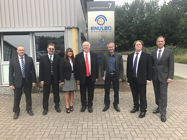
恩莱克成为ERA的认证成员
ERA秘书长James Siever访问了位于德国特里淘市的Enulec GmbH公司,并颁发了该公司的正式会籍证书。
在此背景下,Siever先生写了一篇关于Enulec公司成立与发展的文章:
微软的成功故事已经家喻户晓,成立于车库并发展成为世界一流公司,改变了全球通信行业。Enulec的故事没有这么壮观,我们也成立于车库,并逐渐发展为全球领先的静电消除系统供应商。我们的系统通过创造最佳油墨转移量来消除丢点,漏印情况。Hebertus Dettke,曾就读于电子工程专业,与他的妻子一起创立了Enulce, 从车库创立至今,Enulec已成立36年。
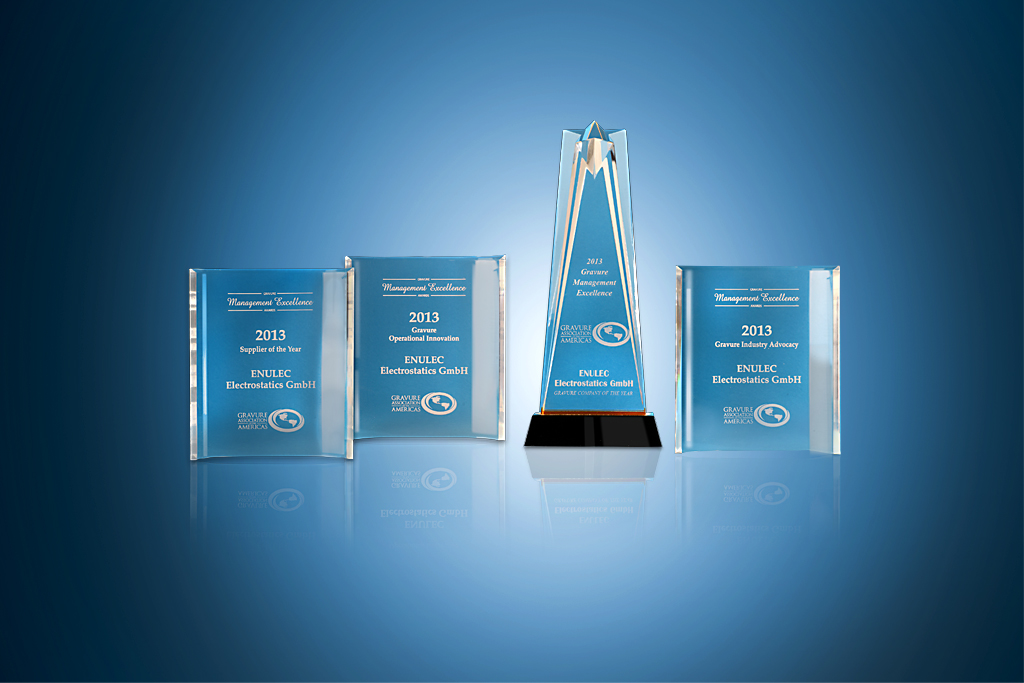
2014 管理卓越奖得主
凹版操作创新奖: 恩莱克
到2014年,恩莱克完全创造了凹印行业的历史,我们的ESA系统不仅仅集成在一家印刷机设备制造商的PLC中,而是所有主要的三家欧洲凹印设备制造商的PLC程序中都集成有我们的系统。
多年来,全球市场领先的凹版印刷机制造商:德国(W&H),意大利(Bobst-Rotomec,Cerutti以及,Uteco),对于恩莱克创新型的ESA以及静电消除系统都信赖有佳。其主要原因是,恩莱克公司的系统确保了最高的效率、安全的生产和经济的印刷以及完善的操作,并与上述制造商和研究机构密切合作,不断开发新技术,以提高凹版印刷机的可靠性和操作友好性。为此,设备制造商决定将恩莱克的静电产品完全集成到他们的PLC中。